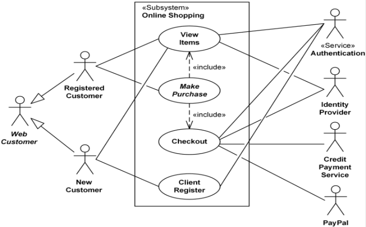

Object diagram – These diagrams show objects and how they relate and interact with each other.

Package diagram – Package diagrams show components as bundles of information, which makes organization more manageable.Ĭlass diagram – The most common UML diagram type, class diagrams show the associations between classes and interfaces.ĭeployment diagram – Deployment diagrams are used to show real world entities, such as servers, and the deployment of nodes within the system.

Profile diagram – This diagram type extends the UML model using stereotypes, which allows for the creation of certain domains and platforms. Here are a few of the most common UML diagram types.įor more detailed information on UML diagrams, check out our article on UML diagram types. There are two types of UML diagrams: structural and behavioral. There are many types of UML diagrams, all with different functions, yet using very similar symbols. Anyone can learn to read and use UML, regardless of whether they’re in the software development field or not. Planning a software system is a crucial step that cannot be skipped, much like how architects and construction workers cannot build a house without a blueprint. UML, short for Unified Modeling Language, is a set of agreed upon notations, shapes, and symbols that tell the reader what components exist within a software system, their attributes, and how they relate to each other. Both are able to be read by anyone with relative ease. UML is a series of symbols and shapes that help to visualize how software systems are organized, and ERDs show the relationships of entities within databases. Making a diagram beforehand helps developers see what components are needed, and how the system or database will be structured. UML and ERDs are both used by software developers to map out software systems and databases before any actual coding occurs.


 0 kommentar(er)
